
SEARCH WHAT YOU WANT

Thermal Vacuum Test Chamber
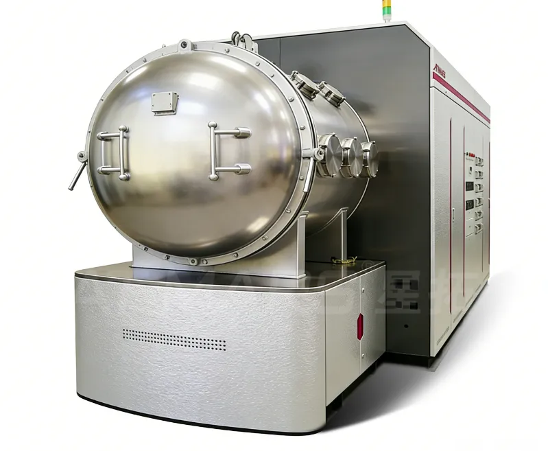
Technical Specifications of High-Precision Vacuum Test Chamber
Vacuum Performance and Sealing
- Control Accuracy: The vacuum control accuracy is $\pm 0.01 \text{ Pa}$.
- Sealing Design: The chamber utilizes a high-sealing structural design with imported sealing components, ensuring long-term vacuum retention with an extremely low leakage rate, suitable for simulating low-pressure and vacuum operating conditions.
Multi-Parameter Control System
- Parameter Regulation: Supports synchronous regulation of vacuum level, temperature, and gas filling (inert gas optional).
- Control Core: Utilizes a PLC intelligent control system and high-sensitivity multi-point sensors to achieve real-time monitoring and automatic closed-loop adjustment of test parameters.
- Temperature Accuracy: Under vacuum conditions, the temperature control accuracy reaches $\pm 0.5^\circ\text{C}$.
Chamber Structure and Materials
- Inner Chamber Material: The inner cavity is constructed from high-purity 304 or 316 stainless steel with a mirror-polished finish. This design offers corrosion resistance, ease of cleaning, and minimizes particulate contamination, making it suitable for precision component testing.
- Shell and Pressure Bearing: The outer shell and pressure-bearing structure employ high-strength alloy steel welding and integral forming. This ensures deformation resistance and high pressure-bearing capacity, adapting to pressure differentials in long-term ultra-high vacuum conditions.
Operation Interface and Safety Protection
- Human-Machine Interface: Features a touch screen interface supporting one-touch of preset programs, real-time data curve display, and historical data export (CSV/Excel/PDF formats).
- Safety Mechanisms: Integrates over-temperature alarms, vacuum anomaly warnings, and power-failure memory functions.
- Interlock Protection: Equipped with automatic pressure relief devices and door interlock protection mechanisms to prevent operational errors.